

VFD induced voltage: 5 critical fixes for reliable motors
Preventing motor failure: The importance of shaft grounding technology
Introduction to VFD-induced shaft voltage and downtime risks

Variable Frequency Drives (VFDs) have transformed industrial operations. They offer precise motor control and significant energy savings, making them indispensable in countless applications. However, this powerful technology introduces an often-overlooked challenge: VFD induced voltage.
This hidden electrical phenomenon can severely shorten the lifespan of electric motor bearings. Without proper mitigation, VFD-driven motors can experience catastrophic bearing failure in as little as 3 to 12 months. This leads to costly unplanned downtime, production losses, and extensive repair bills. For a broader understanding of how to Prevent VFD Induced Bearing Damage, consider consulting comprehensive guides on the topic.
In this comprehensive guide, we will delve into the mechanisms behind VFD induced voltage. We will explore how it generates damaging electrical currents within motor shafts and bearings. Most importantly, we will outline proven strategies and best practices to Prevent VFD induced voltage and protect your valuable motor assets. Our goal is to help you maintain continuous, reliable operation and avoid premature motor failure.
How PWM switching and common-mode voltage generate shaft potential
The core of VFD operation lies in Pulse Width Modulation (PWM) technology. VFDs convert the incoming AC power to DC, then use insulated-gate bipolar transistors (IGBTs) to rapidly switch this DC voltage on and off, creating a variable frequency, variable voltage pseudo-AC output. While effective for motor control, this high-speed switching generates a non-sinusoidal waveform with fast voltage rise times (dV/dt) and high-frequency content.
This rapid switching creates what is known as common-mode voltage. Unlike balanced three-phase power where voltages sum to zero, the VFD’s output phases rarely sum to zero at any given instant. This imbalance results in a net voltage potential between the motor’s neutral point and ground. This common-mode voltage acts as a high-frequency voltage source, driving displacement currents through the motor’s parasitic capacitances.
These parasitic capacitances exist between the stator windings and the rotor, between the rotor and the motor frame, and along the motor cables. As the common-mode voltage rapidly changes, it charges and discharges these capacitances, inducing a voltage onto the motor shaft. This shaft voltage seeks the path of least resistance to ground, which, unfortunately, often includes the motor bearings. Understanding these mechanisms is crucial to comprehending Why Motors Experience Bearing Damage with VFDs.
In some cases, the VFD’s pulsed output can also lead to voltage magnification at the motor terminals, reaching levels significantly higher than the nominal supply voltage, potentially stressing motor insulation. For instance, a 460V system might see terminal voltages up to 1200V. This phenomenon is often exacerbated by longer motor cables and faster IGBT rise times, as detailed in various Tech Notes on VFD effects. Industry standards like NEMA MG1 Part 31 address the insulation requirements for inverter-duty motors to withstand these voltage stresses, but bearing protection requires additional considerations. For more in-depth information on the underlying physics, exploring Shaft Voltage and Bearing Currents can be highly beneficial.
The two main types of VFD-induced bearing currents
When VFD-induced shaft voltage exceeds the dielectric strength of the bearing lubricant film, it discharges through the bearings, causing electrical damage. This typically occurs when shaft voltages reach approximately 5V peak (10V peak-to-peak), though discharges can happen at 20-30V or more. These discharges manifest in two primary forms:
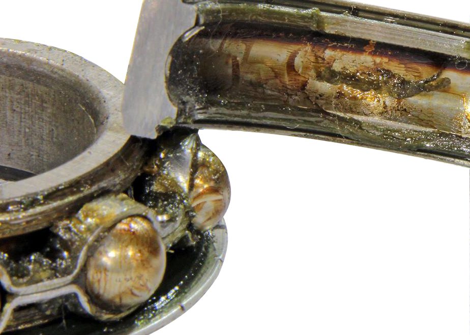
- Capacitive electrical discharge machining (EDM) Currents: These are rapid, high-frequency discharges that occur as the shaft voltage builds up and then suddenly breaks down the lubricant film. Each discharge creates a tiny pit on the bearing raceway and rolling elements, akin to miniature arc welding. Over time, millions of these micro-pits accumulate, causing a “frosted” appearance. This progressive damage leads to premature grease degradation, increased friction, noise, vibration, and ultimately, bearing failure. This type of damage can affect all VFD-driven motors, regardless of size. The majority of motor bearings experiencing this type of VFD-induced current damage fail after 3 to 12 months of operation without mitigation.
- High-frequency circulating currents: These currents occur in larger motors, typically those above 100 HP (75 kW). In these motors, the common-mode flux within the motor can induce an axial voltage along the shaft, creating a complete high-frequency current loop. This current flows from the shaft through one bearing to the motor frame, and then back through the other bearing to the shaft. These circulating currents can cause significant damage to both bearings.
Both types of bearing currents drastically reduce the motor’s L10 life, which is the expected operating life before 10% of bearings fail. Instead of lasting years, bearings can fail in months. The visual evidence of this damage, such as frosted bearing raceways and degraded grease, is a clear indicator of electrical bearing damage. For a comprehensive overview of these phenomena, including common-mode voltage fixes, refer to VFD Induced Bearing Currents: Common Mode Voltage Fixes.
Integrating shaft grounding into modern motor maintenance
To combat the pervasive threat of VFD-induced bearing damage, proactive maintenance strategies are essential. Relying solely on reactive repairs leads to costly downtime and reduced operational efficiency. Integrating effective electrical protection into a motor maintenance program is critical for overall system reliability.
Electro Static Technology, a leader in bearing protection solutions, manufactures AEGIS Shaft Grounding Rings. These innovative devices provide a proven, low-resistance path for shaft voltages to safely discharge to ground, bypassing the motor bearings entirely. For more information on the company, you can visit their profile at Electro Static Technology: Mechanic Falls, ME 04256. By diverting these harmful currents, AEGIS rings effectively prevent electrical bearing damage, extending motor life, and ensuring continuous operation. This approach is a cornerstone of Preventing VFD AC Drive Induced Electrical Damage to AC Motor Bearings.

Proactive motor maintenance: Measuring and confirming shaft voltage
The first step in addressing VFD-induced bearing currents is to determine if your motors are at risk. This involves measuring shaft voltage in the field. While measuring the actual bearing current can be complex and requires specialized lab equipment, measuring shaft voltage provides a practical and effective diagnostic tool.
Technicians can use a digital oscilloscope equipped with a conductive microfiber probe to accurately capture the high-frequency voltage waveforms on the motor shaft while the motor is running. The probe makes contact with the rotating shaft, and the oscilloscope displays the voltage potential between the shaft and the motor frame.
A critical threshold for shaft voltage is 5V peak (equivalent to 10V peak-to-peak). Shaft voltages consistently above this level are considered likely to cause electrical discharge damage in motor bearings. If measurements reveal voltages in this range, immediate mitigation is necessary. Even if direct current measurement is difficult, Ohm’s Law allows us to infer the presence of damaging currents from these voltage readings. For practical guidance, the AEGIS Bearing Protection Handbook for VFD Fed Motors offers detailed testing procedures.
Shaft Voltage Level (Peak) Risk of Electrical Discharge Damage Recommended Action Below 5V Low Continue monitoring 5V – 10V Moderate to High Implement mitigation strategies (e.g., shaft grounding ring) Above 10V Very High Immediate implementation of comprehensive mitigation (e.g., grounding ring + insulation) The Role of Shaft Grounding Rings in Motor Maintenance Programs
Shaft grounding rings, particularly those featuring advanced conductive microfiber technology, are a highly effective solution for preventing VFD-induced bearing damage. These rings are designed to provide a continuous, very-low-resistance path from the motor shaft to the motor frame, diverting harmful currents away from the bearings.
Unlike traditional carbon brushes, conductive microfibers offer thousands of contact points, ensuring consistent conductivity and superior wear life, often rated for 200,000 hours of continuous operation. This robust design makes them suitable for demanding industrial environments.
Installation can be internal (within the motor housing) or external, depending on the motor design and application. Proper shaft preparation, such as cleaning the shaft to bare metal and applying a colloidal silver coating, ensures optimal conductivity and long-term performance. For specific applications like HVAC systems, robust Grounding of HVAC Motor Shafts Protects Bearings Lowers Repair Costs is crucial. Furthermore, detailed guidance on Bearing Protection Best Practices and Installation can help ensure correct implementation. For specialized environments, a Technical Bulletin Shaft Grounding in Hazardous Environments is also available.
By providing this alternative discharge path, shaft grounding rings neutralize the damaging effects of VFD-induced voltages, dramatically extending bearing life and preventing costly motor failures. This technology is a critical component for any motor considered To Be Considered True Inverter Duty Motors Need Bearing Protection.
Mitigation strategies and best practices for plant reliability
Achieving maximum plant reliability in VFD-driven systems requires a multi-faceted approach to electrical protection. Combining shaft grounding with other best practices creates a robust defense against common VFD-induced problems, minimizing downtime and extending equipment lifespan.
Here are key mitigation steps for comprehensive system protection:
- Install shaft grounding rings: Essential for all VFD-driven motors to divert common-mode induced shaft voltages away from bearings.
- Utilize insulated bearings: For larger motors (above 100 HP), insulate the non-drive end bearing to block high-frequency circulating currents.
- Employ VFD-rated shielded cables: Use cables designed for VFD applications with proper 360-degree shield terminations to minimize electromagnetic interference and common-mode current.
- Ensure proper grounding and bonding: Implement robust, low-impedance grounding throughout the system to provide a stable reference and dissipate stray currents.
- Consider common-mode chokes/filters: These can reduce common-mode current by up to 65% in many VFD systems, further mitigating bearing current risk and other VFD-related issues.
- Minimize cable lengths: Keep motor cable runs as short as practically possible to reduce parasitic capacitance and voltage magnification.
- Regular monitoring: Periodically measure shaft voltage and inspect bearings as part of a proactive maintenance schedule.
For more information on how AEGIS rings are applied in various motor lines, refer to the Application Note Motor Lines with AEGIS Shaft Grounding Rings. It’s also worth noting that AEGIS Shaft Grounding Rings Provide Both Contact and Noncontact Grounding. The IEEE Application of Static Charge Dissipation to Mitigate Electric Discharge Bearing Currents also offers valuable insights.
Protecting large motors: Insulated bearings and circulating currents
While shaft grounding rings are effective for preventing capacitive EDM currents in all motor sizes, larger motors (typically above 100 HP or NEMA frame 404T and greater) present an additional challenge: high-frequency circulating currents. As previously discussed, these currents flow axially through the shaft and bearings.
To effectively block these circulating currents, it is best practice to insulate one of the motor’s bearings, typically the non-drive end (NDE) bearing. This breaks the current path, forcing the circulating currents to find an alternative, non-damaging route. Common insulation methods include ceramic-coated bearings or hybrid bearings (with ceramic balls), which offer megohm-level insulation and high breakdown voltage.
For comprehensive protection in large motors, combining a shaft grounding ring on the drive end (DE) with an insulated bearing on the NDE is often the recommended solution. This dual approach addresses both capacitive EDM currents and high-frequency circulating currents, providing the highest level of bearing protection. It’s also important to consider potential issues like partial discharge in motor windings, which can be exacerbated by VFDs, and for which further technical deep dives are available, such as Partial Discharge Mechanisms.
Beyond bearing protection, other VFD-related electrical issues can impact overall system health. For example, VFDs can cause nuisance tripping of GFCIs due to leakage currents, especially in multi-drive applications. Understanding these mechanisms and solutions involving isolation transformers and specialized RCDs is crucial for system stability, as explored in articles like VFD GFCI Tripping: Fix Leakage Currents on Isolation Transformers – Industrial Monitor Direct. Similarly, VFDs can produce ground fault currents even on ungrounded delta supplies, a phenomenon explained by high-frequency parasitic capacitances, which is detailed in Why VFD Ground Fault Current Flows on Ungrounded Delta Supply – Industrial Monitor Direct.
Cable selection and conduit isolation to prevent induced voltage on inactive wires
VFD-induced voltage isn’t limited to motor shafts; it can also appear on inactive motor wires sharing the same conduit or running in parallel with active VFD-driven motor cables. The high-frequency, pulsed output of VFDs creates electromagnetic fields that can induce voltages onto adjacent conductors, even if those conductors are connected to motors that are currently off or are spare wires.
Real-world measurements have shown induced voltages of 32V to 40V on inactive motor wires sharing conduit with VFD-driven motors. Such voltages pose a safety hazard to technicians performing maintenance, as an unexpected shock can occur even on seemingly “dead” circuits. This phenomenon is a common topic of discussion among professionals, as highlighted in forums like VFD inducing voltage on nearby wires | Electrician Talk.
To mitigate this risk and prevent potential safety issues, several best practices should be followed:
- Separate conduits: Ideally, each VFD-driven motor should have its own dedicated conduit. This physically separates the VFD output cables from other wiring, minimizing electromagnetic induction.
- VFD-rated shielded cables: If separate conduits are not feasible, use VFD-rated shielded cables. These cables are designed with an overall shield (often copper braid or foil) that contains the electromagnetic fields, preventing them from inducing voltages onto adjacent conductors. Crucially, these shields must be terminated with a 360-degree connection at both the VFD and motor ends to be effective. Pigtail ground connections are generally ineffective for high-frequency common-mode currents.
- Minimize parallel runs: Avoid running VFD output cables in parallel with other control or power cables for extended distances, even in separate conduits, if possible.
- Load reactors: For longer cable runs (e.g., over 100 feet), consider installing load reactors at the VFD output. These devices help to smooth the VFD’s waveform, reducing the dV/dt and, consequently, the electromagnetic interference that causes induced voltages.
Implementing these cabling and conduit isolation strategies not only enhances safety but also improves the overall electromagnetic compatibility of the industrial environment, preventing interference with sensitive control systems.